For a downloadable Adobe Acrobat (.PDF) version of our Limited LIFETIME WARRANTY,
go to our website at www.ddtechglobal.com
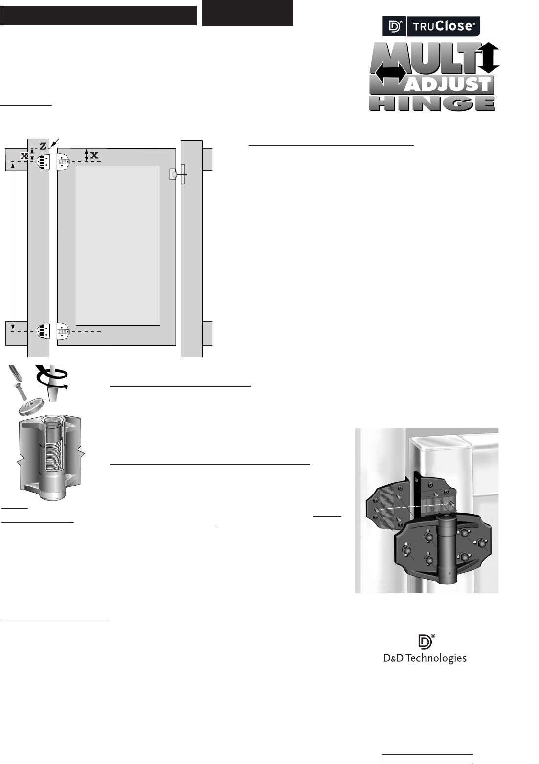
A
Hinge Post
Gate Frame
Latch Post
B
C
D
Mark
Keep hinges as far apart as practicable
Step 1 – Install 4 MOUNTING BRACKETS
Note that each mounting bracket holds three stainless steel threaded
studs. The middle (or ‘outside’) stud indicates the center of each bracket;
use this stud as a means of centering and leveling Brackets A and B
(and C & D), as indicated by the dashed lines (Figure 1).
1. Determine the location of the gate in the mounted position. On the hinge
post, mark the top of the gate, as shown at point ‘Z’.
2. From this point, measure down the desired distance [X] for the location
of Brackets A and B – and up the same distance from the bottom of the
gate for Brackets D and C. (Note that the top of the smaller brackets B and
D should never be installed closer than 1
3
/16" (30mm) from the top and
bottom of the gate respectively.)
3. Using the 1"x10g self-drilling, wafer-head screws supplied, first (for a
L-H hinged gate as shown in Figure 1) fix Brackets A and C to the gate
frame, and then fix Brackets B and D to the hinging post. (For a R-H hinged
gate fit B & D to the gate and A & C to the hinge post.)
Each Bracket has six screw holes: four at the front and two in the side
fixing leg. If a vinyl gate has aluminum reinforcing thicker than
1
/8" (3mm),
or steel of any thickness, the screws will require
5
/32" (4mm) ‘pilot’ holes.
MAINTENANCE & REQUIREMENTS:
• Always use two MULTI-ADJUST hinges on any one gate.
• Ensure the gate does not swing beyond 180°.
• Each hinge must have equal tension at all times.
• Remove all other types of hinges and self-closing devices.
• Do not lubricate or disassemble these hinges at any time.
• Never remove MULTI-ADJUST hinges from gate until spring
tension is released.
INSTALLATION INSTRUCTIONS
Some important points concerning the installation of MULTI-ADJUST HINGES:
• The larger brackets A & C are always to be located on the right-hand side.
(This ensures the tension adjustor is always facing up for easy adjustment).
• The hinges should be installed as far apart as is practicable for optimum performance.
• Minimum gap between hinge post and gate:
5
/8" (16mm); Maximum gap: 1
3
/8" (35mm).
Tools required: Electric drill/cordless drill (use low clutch settings), drill bits, Phillips No. 2 screwdriver
(hand & power), large slot-head screwdriver and
7
/16" wrench (preferably 6" long).
Step 4
ADJUST TENSION
Remove end cap. Use large
screwdriver to depress and
turn spring-loaded adjustor
counterclockwise. Hold
desired tension and allow
to rise back into retention
sleeve. Replace cap.
suits both left-hand or
right-hand hinged gates
Example of L-H hinged gate
Step 2 – Install MAIN HINGE BODY
1. Take the hinge bodies and place them over the gate Brackets A and C. Use the dome nuts and washers supplied
to secure the hinges finger tight.
2. Have the remaining dome nuts at hand. Take the gate (with hinges attached) and locate the hinges over the post
Brackets B and D. Secure the dome nuts to temporarily fix the gate
into position.
Step 3 – VERTICAL & HORIZONTAL ADJUSTMENT
1. Note that the slots on the right leaf are horizontal and on the left
leaf they are vertical. The gate now needs to be lifted and aligned for
correct operation. Lift gate so that the top of the gate is in line with
point ‘Z’. Firmly tighten the dome nuts on the left-hand leaf. DO NOT
OVERTIGHTEN THE DOME NUTS – thus the suggestion of a 6" wrench.
2. The horizontal slots in the right-hand leaf provide an adjustment
range of
3
/4" (20mm). Use this range to adjust the hinge gap to the
desired position. Fix this position by firmly securing all the remaining
dome nuts using the 6" wrench. Minor alignment adjustments may
be required from time to time.
•INSTRTCHDMA1_21/4/11
TCHDMA00005PA
• Do not physically alter hinge bodies by cut
ting, milling, machining or grinding any part.
• For safety, remove protruding bolts/screws
after installation by cutting, grinding
and/or filing.
Figure 1
MADE IN AUSTRALIA
AUSTRALIA: Unit 6, 4-6 Aquatic Dr, Frenchs Forest NSW 2086
USA: 7731 Woodwind Drive, Huntington Beach, CA 92647
EUROPE: Niasstraat 1, 3531 WR Utrecht, The Netherlands.
www.ddtechglobal.com


 (2 pages)
 Manymanuals.com
 Manymanuals.de
 Manymanuals.fr
 Manymanuals.it
 Manymanuals.pl
 Manymanuals.cz
 Manymanuals.es
 Manymanuals-pt.com
Commentaires sur ces manuels